The Wait
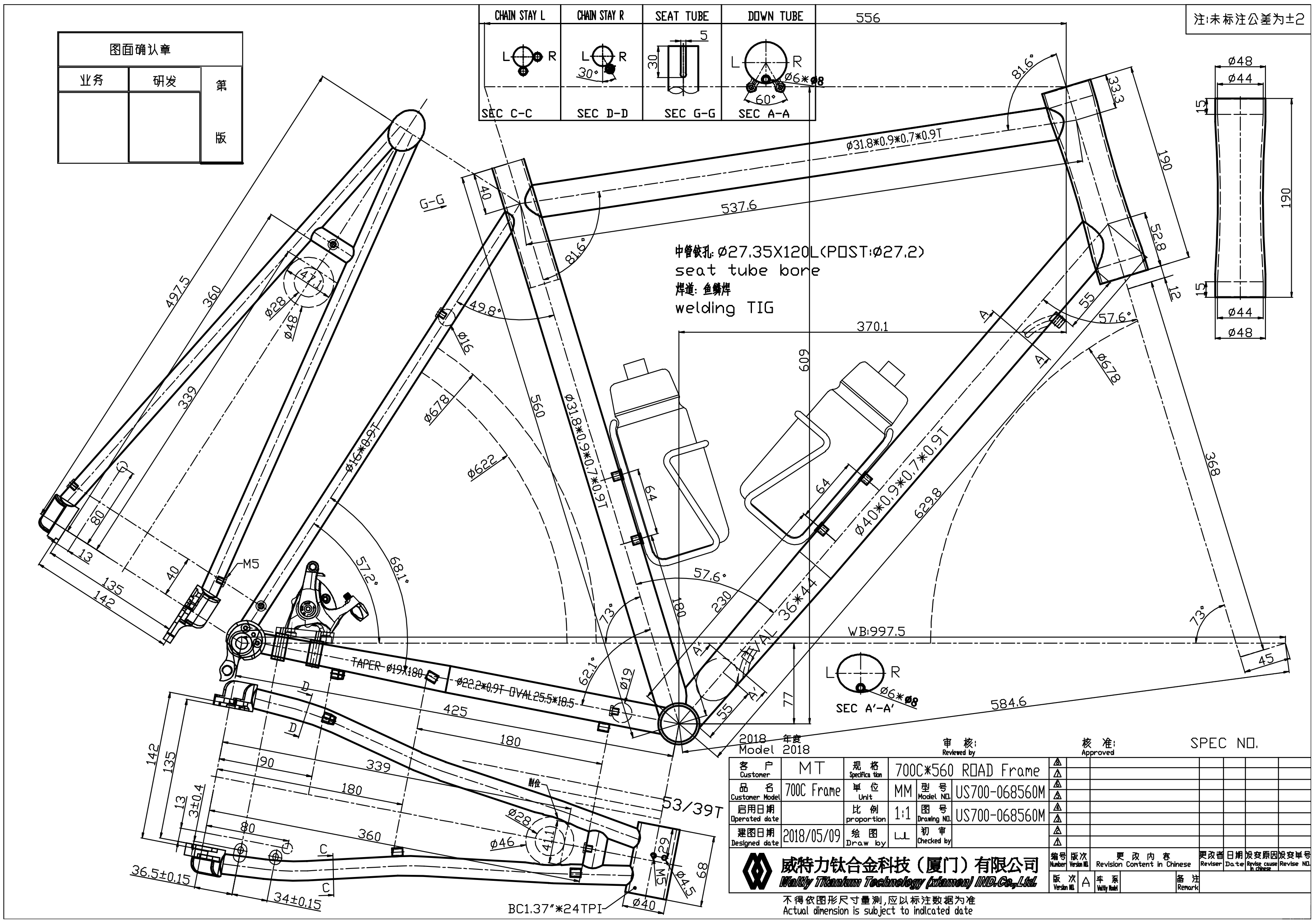
The hardest part of the this journey was definitely twiddling my thumbs waiting for the frame to be completed! I approved the final CAD drawing on May 9th, and Waltly claimed to deliver the frame 30-45 days after final drawing approval. So that meant I should have received it by June 9th-23rd. Unfortunately, it took quite a bit longer than that.
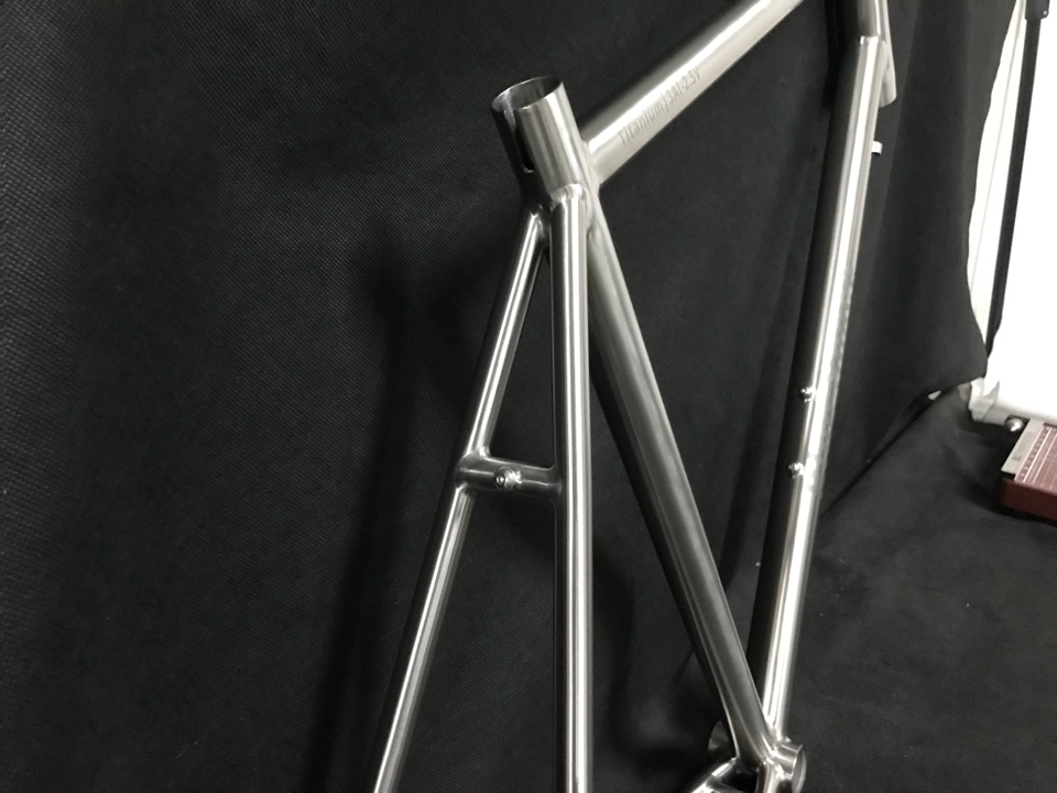
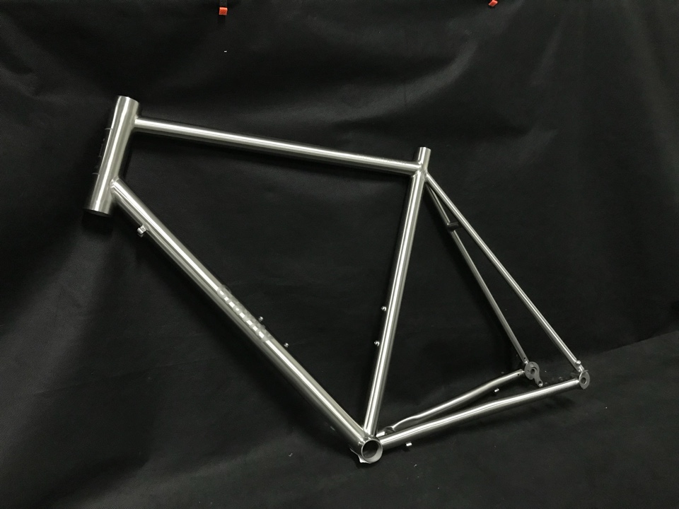
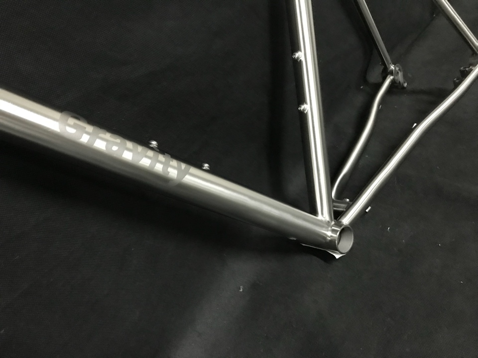
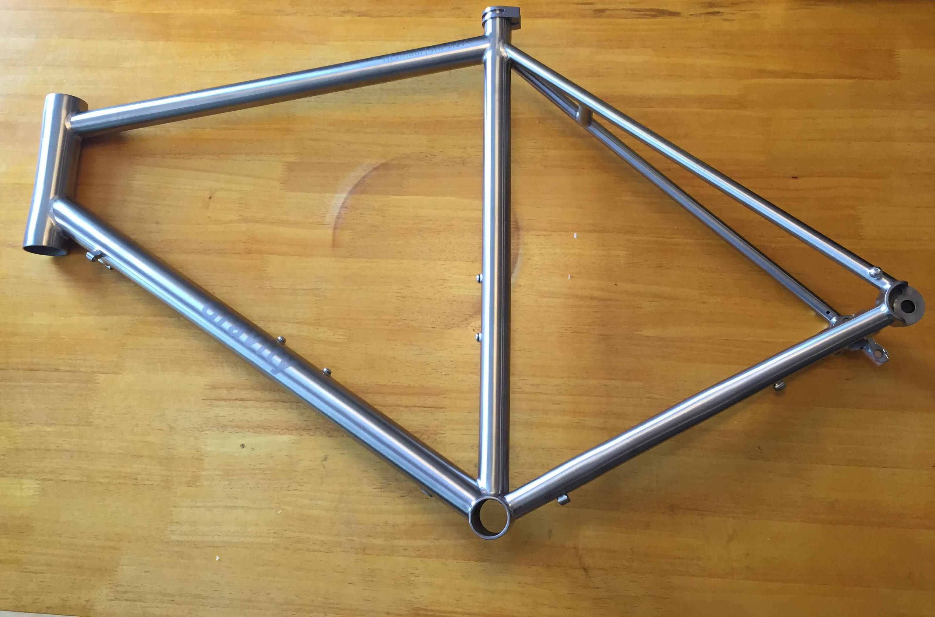
When the target completion dates approached, I sent a an email to Sumi. She kept telling me the frame was almost done for a few weeks, until she eventually informed me that their logo printer was broken, and that they needed to purchase and install a new one. After an additional 2 weeks of waiting, they finally sent me a photo of my completed frame, with decals showing where the bead-blasted logos would be applied. The frame looked good from what I could tell, but there were some issues with the logo placement.
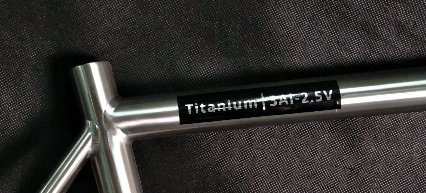
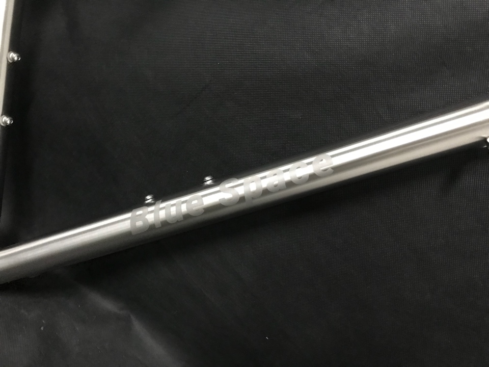
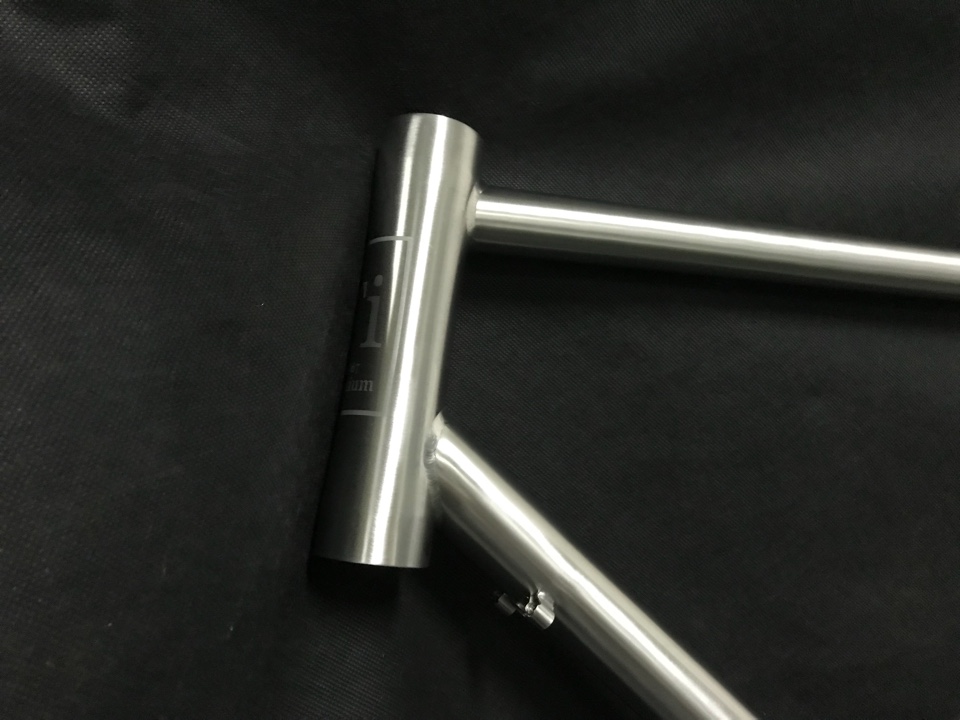
The top tube logo was too far to the right.
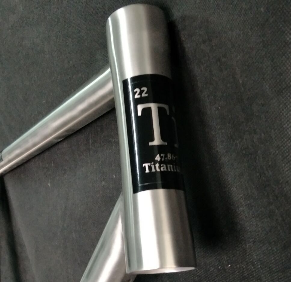
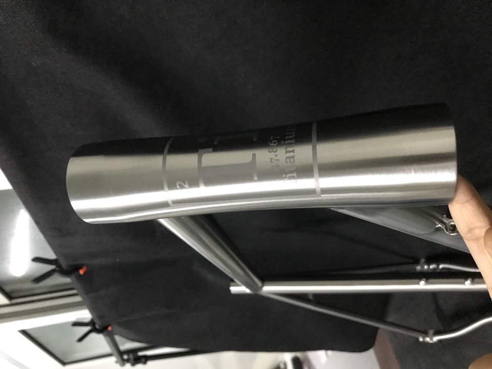
The Ti element logo was missing the prominent rectangular border.
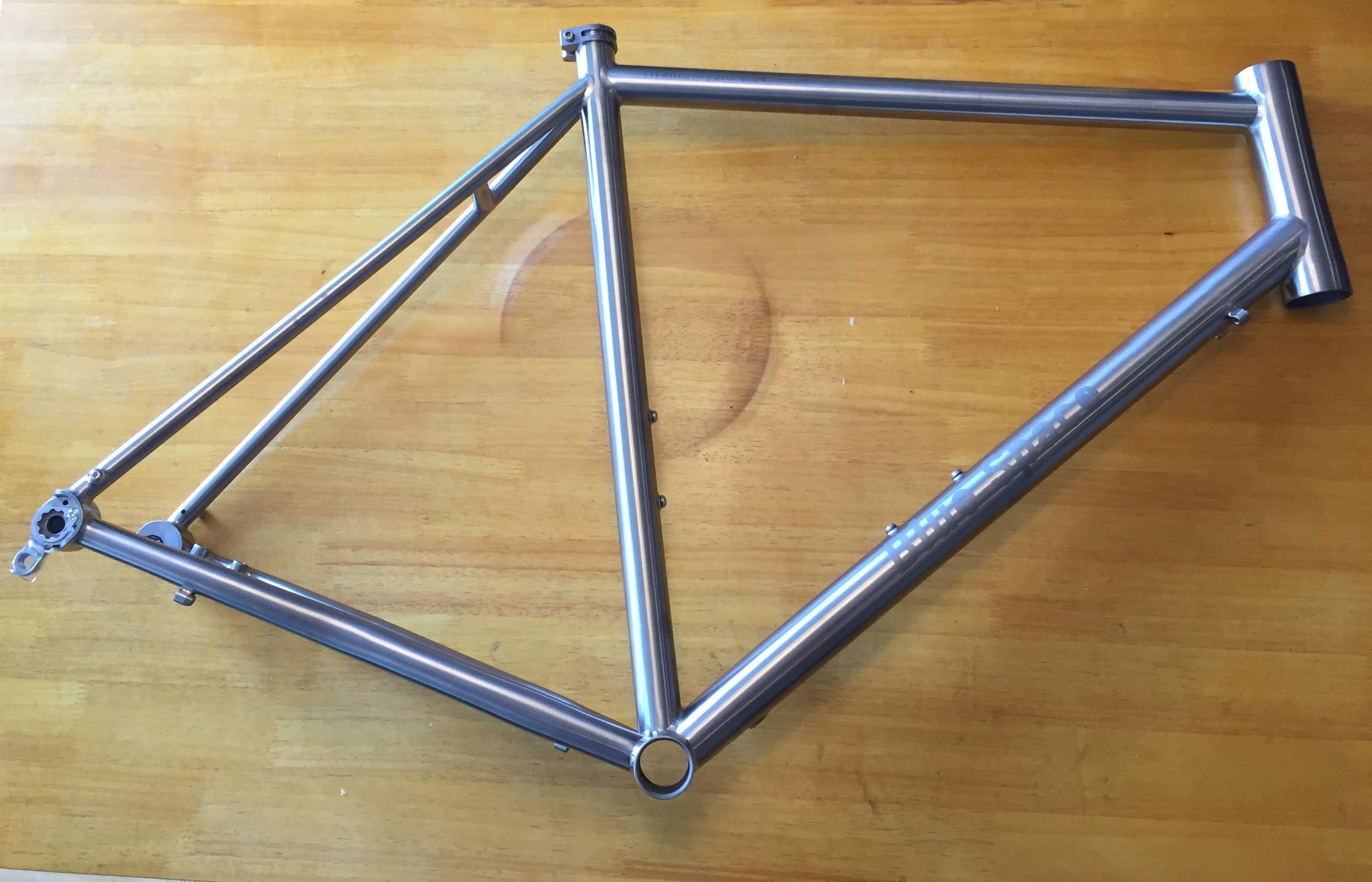
Sumi was glad to reprint and re-position the logos, but it took another week for some reason. I eagerly awaited the final photos:
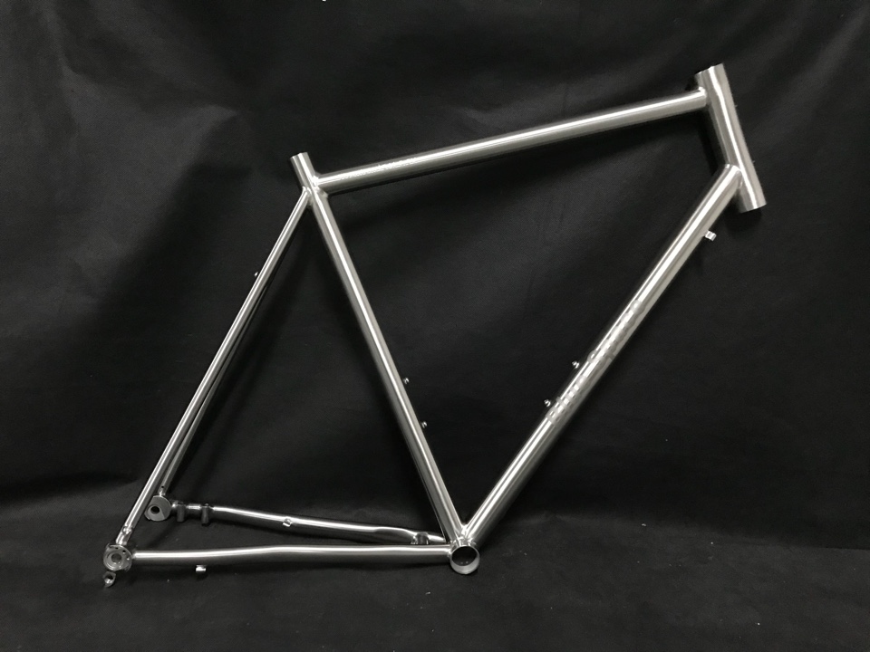
On receiving these beautiful photos of my frame, I immediately sent the remainder of the payment via PayPal, and they shipped it that day via EMS post. EMS is an okay way to ship things from China. Basically, packages wait around until they can be piggy-backed onto commercial flights, and the final leg is completed by local carriers (USPS). Tracking information is pretty sparse. I got a status update on the first day, and then I got another notice a week and a half later that it was in LA and en route to SF.
The final date of arrival was Wednesday July 18th, which was 69 days after final drawing approval, quite a bit longer than the quoted 30-45 days. This annoyed me somewhat, but ultimately I was far too happy to complain now that I finally had my frame.
The Build Day 1
Unboxing
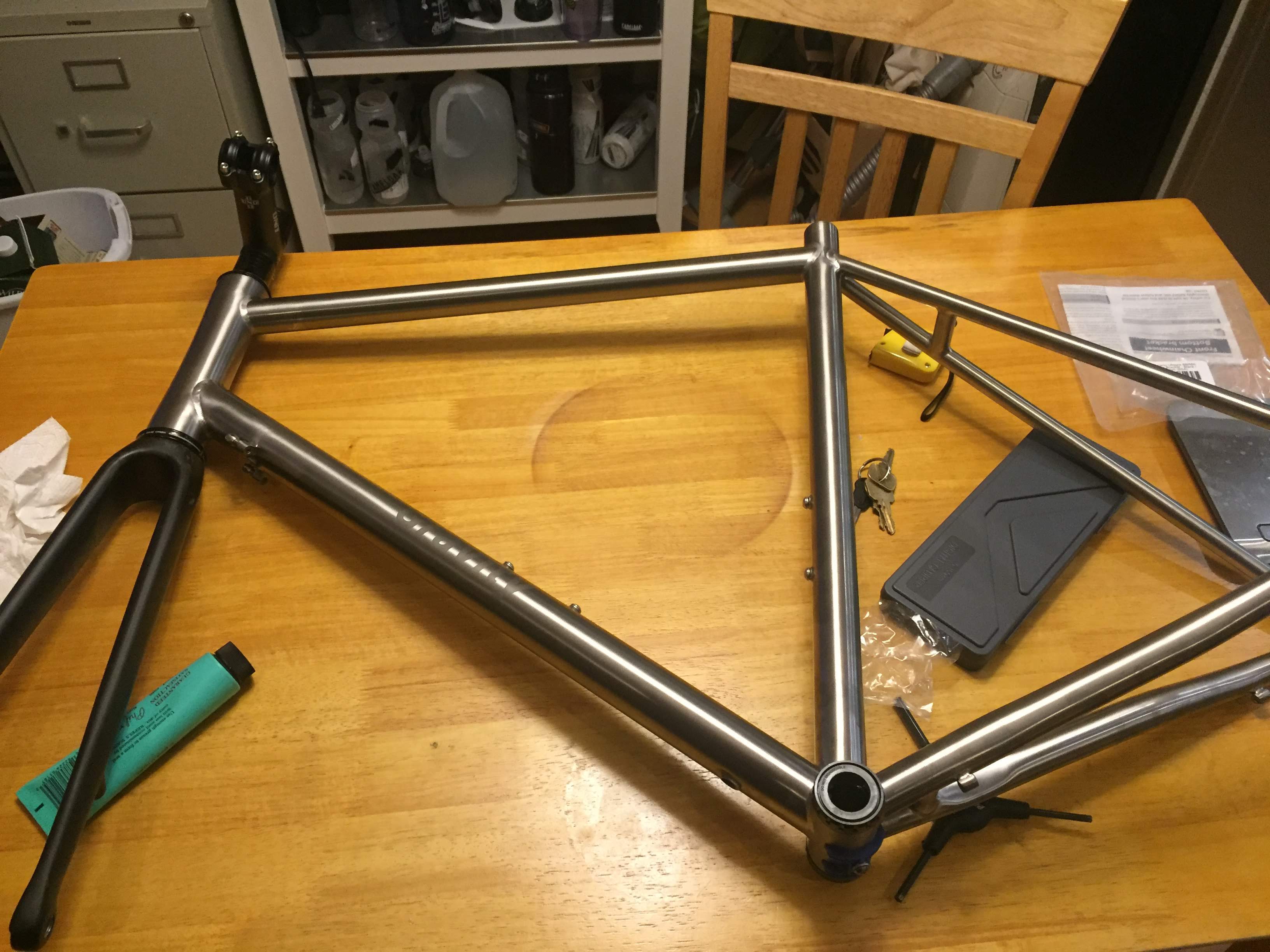
The frame came in a form-fitting box, tightly wrapped in flexible styrofoam material. Although the box was quite big, I was struck by how light it was–I carried it home from my work shipping address on the BART and couldn’t wait to unbox it. Once unboxed, I gave it a quick once-over and everything looked good. Waltly also included a rear thru-axle and a seatpost collar for free, which was very nice of them.
Immediately after, I used my kitchen scale to weigh it: 1720g. That’s a bit higher than I expected, as Sumi estimated 1400g in our initial emails, and other Titanium frames of this size typically get down to the 1500g range. This worried me a little, but it was too late to do anything about it, so I just hoped that the final build would still be around 18lbs as I predicted. Ultimately, I got what I paid for, in this case a $1000 fully custom titanium frame that isn’t going to be as light as one by a western manufacturer that cost 3-4 times as much.

I had been preparing for and anticipating this build for over two months. So right after work, I subsequently grabbed a few key components, slung the frame over my shoulder, and headed straight to the Bike Kitchen for their 6pm opening.
The Bike Kitchen
The Bike Kitchen is a really cool thing you would imagine just in San Francisco. It’s basically a donation + volunteer run scrappy bike repair shop in the middle of a fancy residential apartment complex in the Mission District. It only has a few 3-hour time slots throughout the week where community members can drop in, use tools, and work on their bikes. I really needed this place because even though my roommate (a retired semi-professional biker) has a ton of tools, he doesn’t have everything I needed.
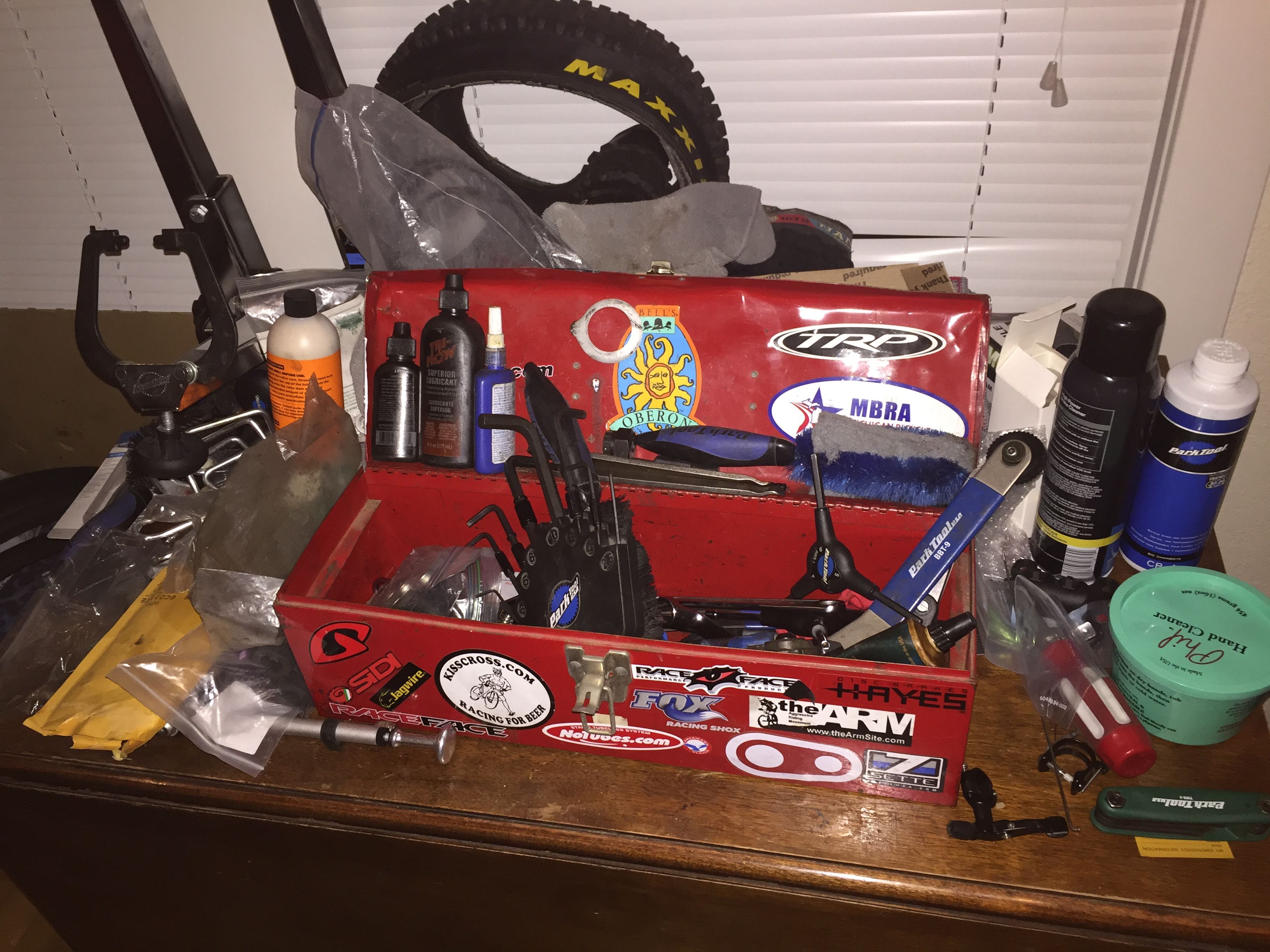
Our apartment workbench, *almost* everything needed to fully assemble a bicycle.
A few weeks prior, I considered whether to pay $50 for a 1 year membership or volunteer 6 hours. $50 isn’t too much, but I figured it might be fun to volunteer and help fix other people’s bikes, so I put in two 3 hour sessions the previous few weeks to receive a 1 year membership.
The 15 minute walk to the Bike Kitchen was on a beautiful still sunny San Francisco evening. I probably had a stupidly wide smile beaming across my face that day. A lady smiled at me and commented “got a project I see ;)”.
I arrived there with the following components:
- my frame
- my carbon fork
- bottom and top headset pieces
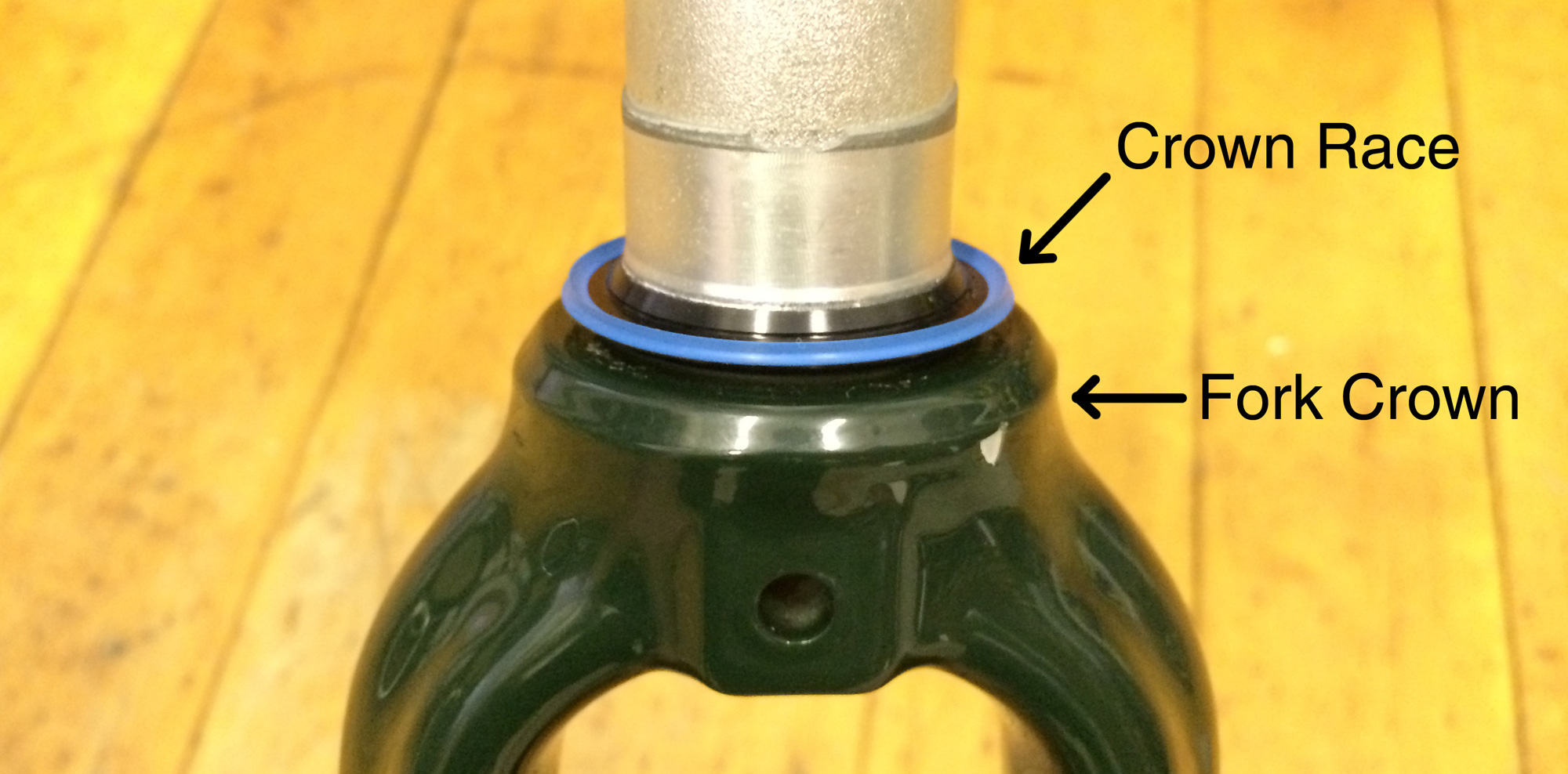
- fork crown race
- steerer compression plug
- stem spacers
- stem
- bottom bracket
Things I needed to do:
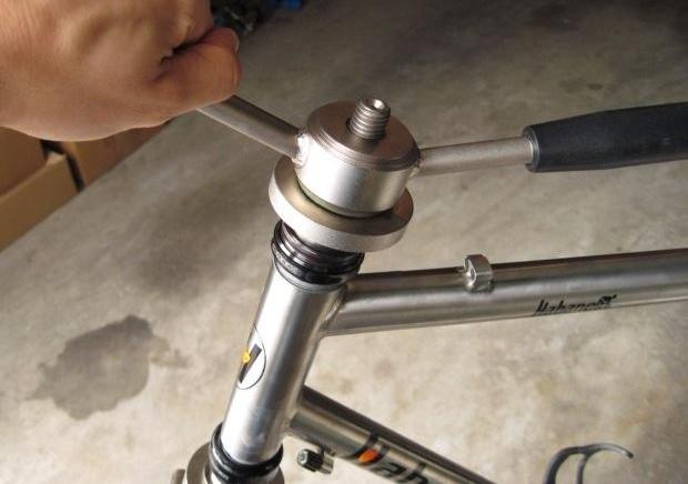
- Install the crown race onto the fork using their crown race tool–basically a hollow cylinder that I used to hammer the crown race into place, providing a smooth surface for the lower headset bearing to rotate over
- I needed their headset tool to press my headset cups into my headtube. The top and bottom headset cups are manufactured to be slightly larger diameter than the inner diameter of the headtube. A tool is needed to apply immense pressure on the cups evenly to press them into place.
- I also planned to use their saw to cut my fork steerer to length, but I ended up leaving this for the next visit, since it’s a permanent change. My general philosophy is to perform all reversible build steps first, while the bike begins to take form. When things are finalized and I gain more confidence that things are correct, I begin doing permanent things.
- Lastly I needed to screw in the bottom bracket–supposedly the simplest task. The usual tool used was too large, and I needed a special adapter that they didn’t have. With only an hour left until closing time, I walked further to the nearest bike shop, Sports Basement. A mechanic from the back came out to help me, installing bottom bracket using the special adapter. He also applied special anti-seize goop, explaining to me that titanium frames need anti-seize for threaded interfaces, not just grease, because titanium has high chemical reactivity when left in contact with steel or aluminum over long periods of time. He did this all for free! I really love Sports Basement.
Once that was done, I walked back home to continue the build with apartment tools.
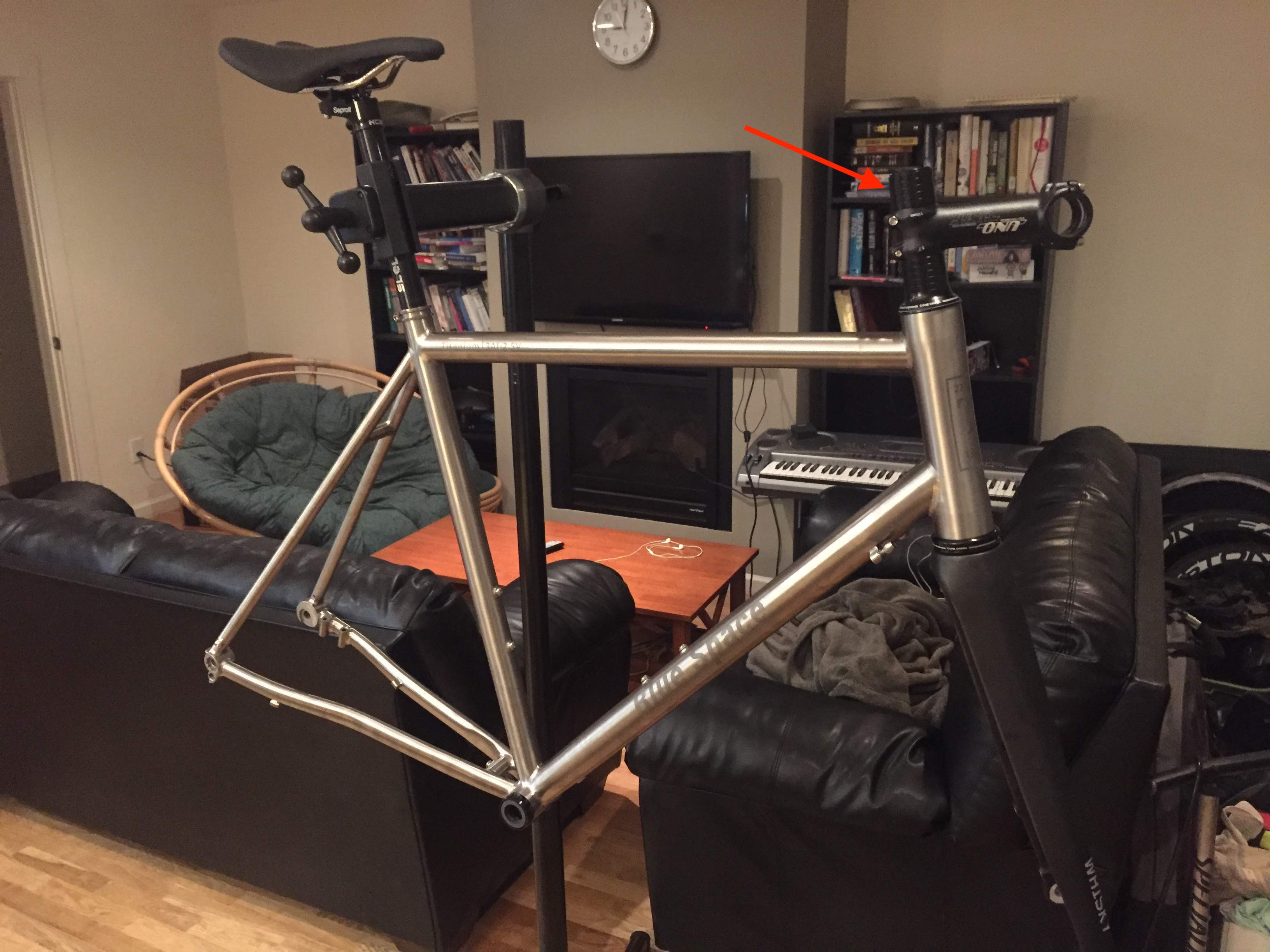
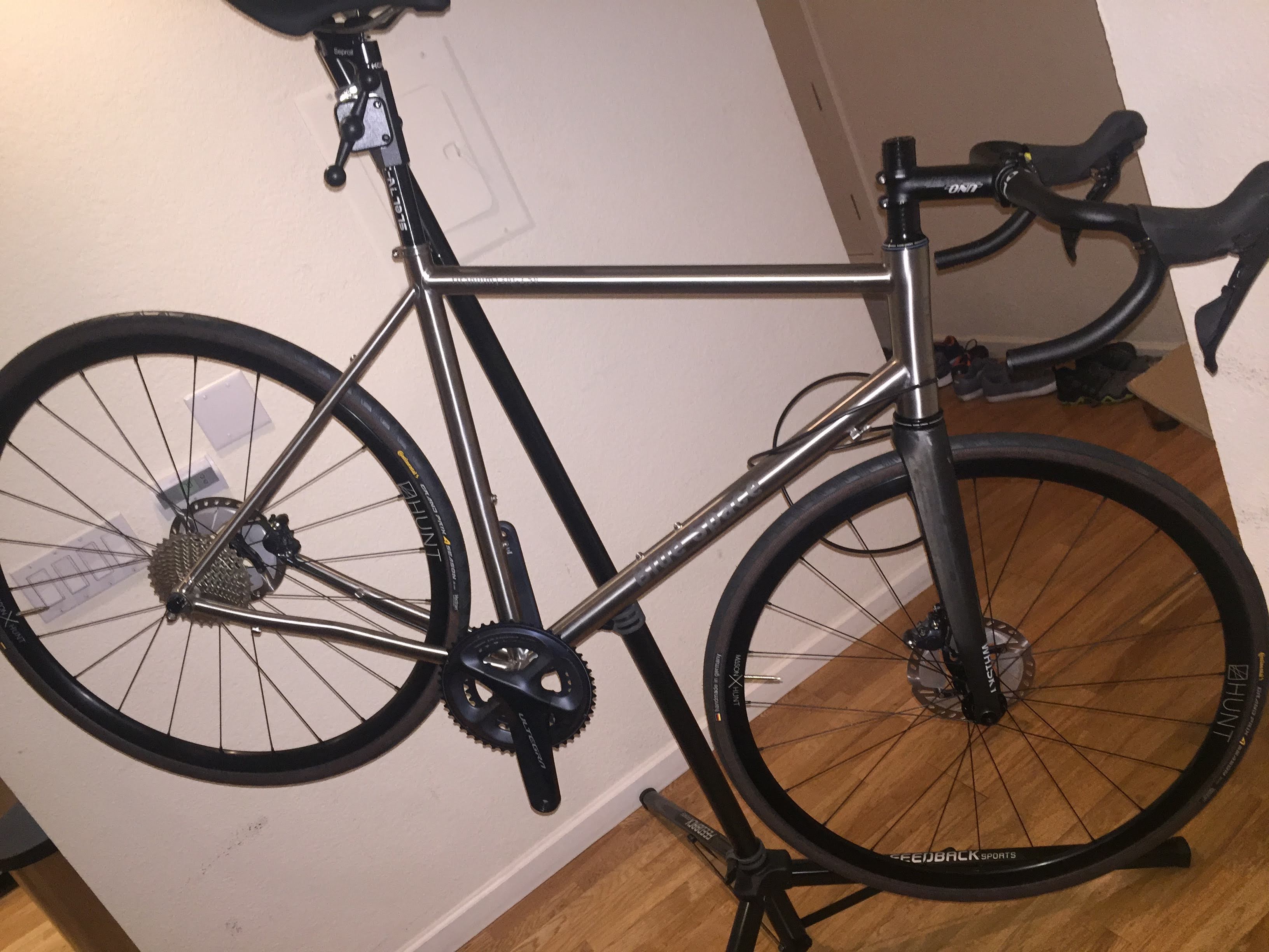
The fork steerer sticks out above the stem and looks funny, but I'll cut that down later.
The rest of the build went together pretty smoothly. My Shimano Ultegra groupset was manufactured to extremely tight tolerances, and the Waltly Titanium frame was equally exact. It was mostly a matter of screwing in parts. By the end of the night, I ran into the most difficult challenge of the build…
Internal Cable Routing
Cable routing in and around a bicycle frame is almost an art in and of itself (see Sheldon Brown or Bike Radar). There are countless options to choose from that strike a compromise between ease of maintenance and the stealthy aesthetic of hidden cabling.
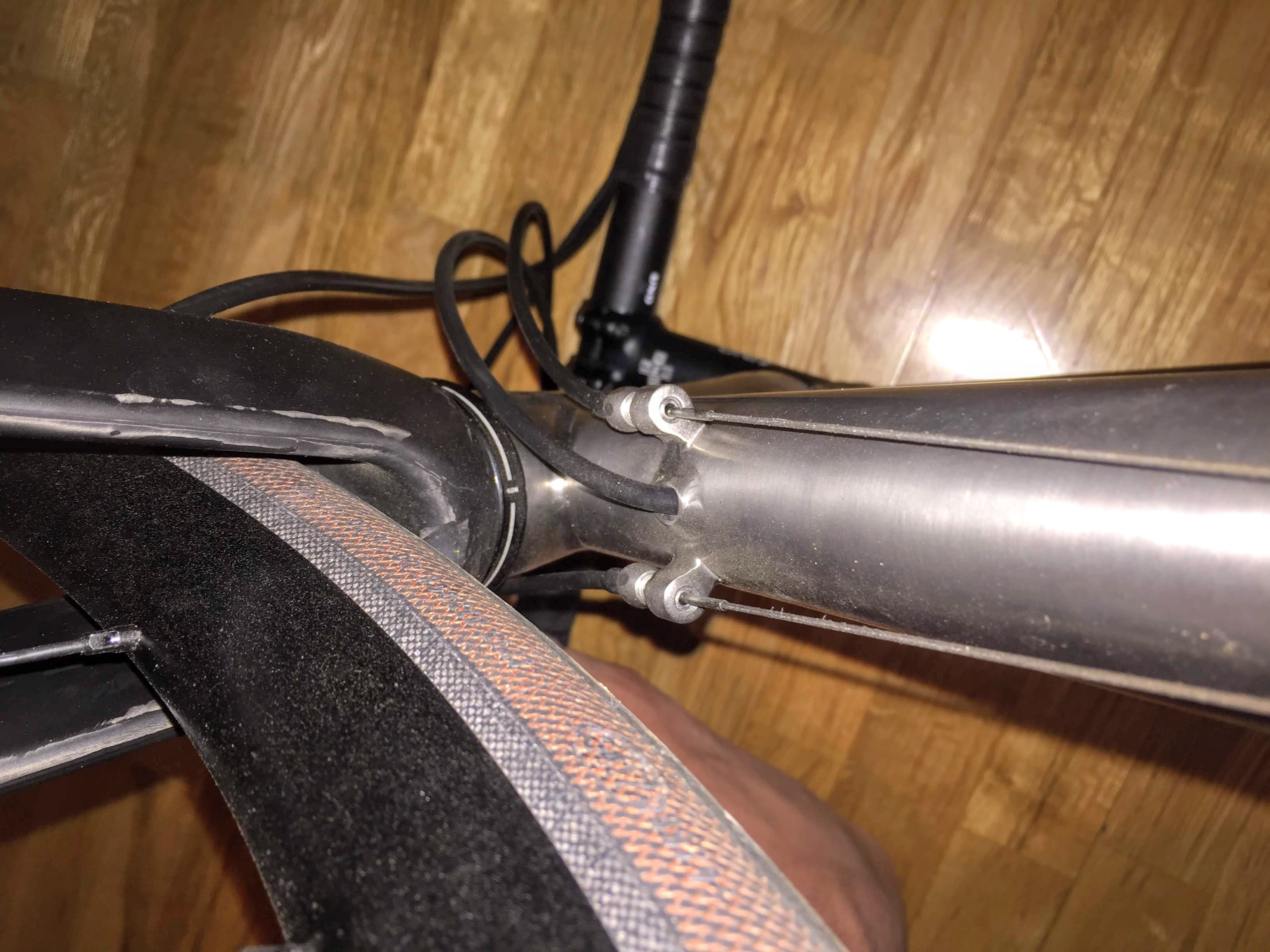
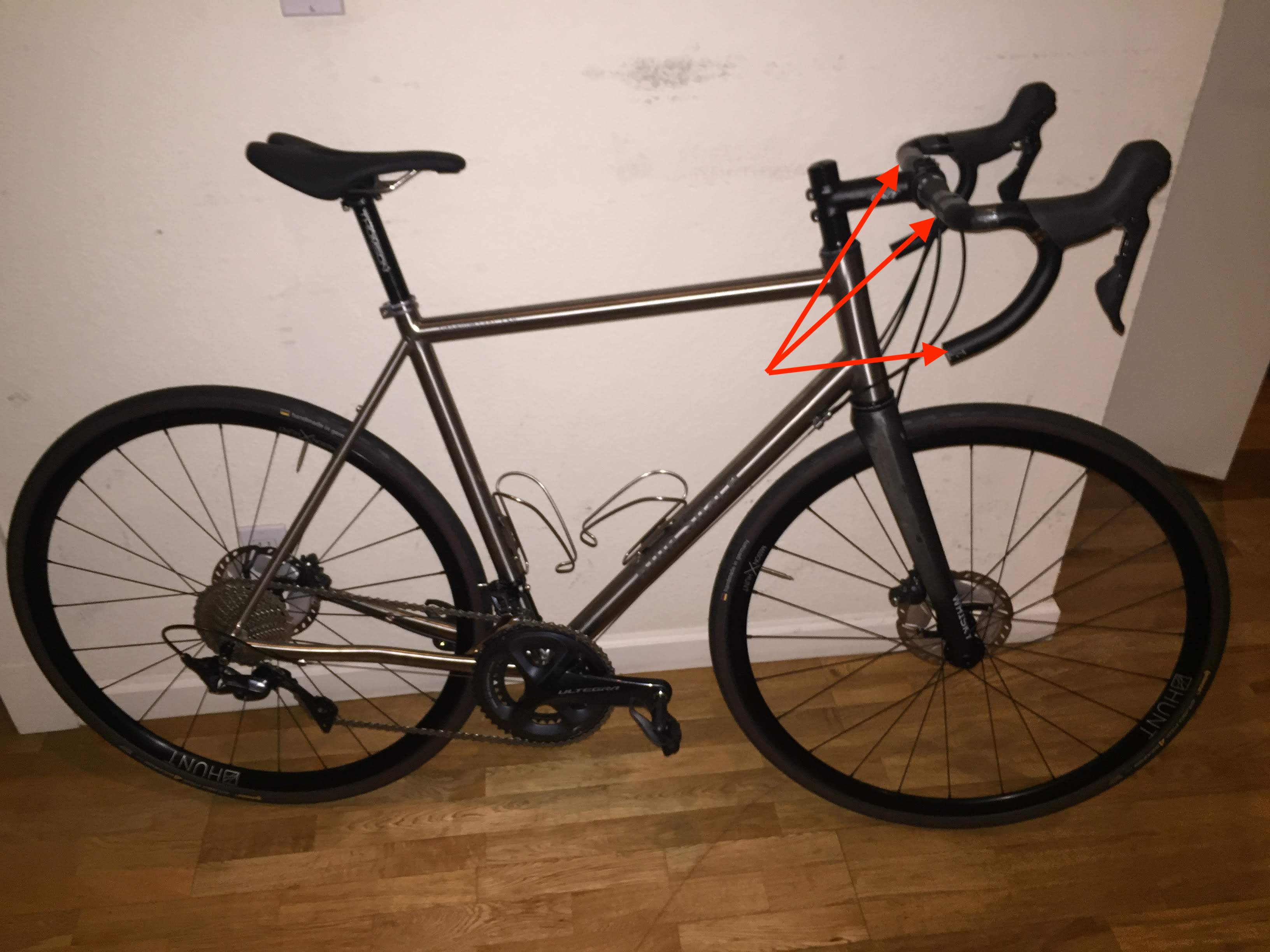
As I mentioned in the first post, I chose criss-cross external shifter cables on the underside of the downtube, with the rear hydraulic cable routed internally through just the downtube so as not to get in the way of the shifters criss-crossing. This had the following advantages/compromises:
- it reduced weight by not requiring full length derailleur outer cables, instead relying on the bicycle frame itself for some part of the cable support
- it was aesthetically quite nice, since it didn’t have three thick cables running along the downtube, only 2 thin barely perceptible inner cables and a single thick hydraulic cable that is routed inside the frame
- the criss-crossing allows a more natural curve of the cables at the front of the bike, reducing cable rub
- it didn’t require the more exotic bottom bracket + chainstay routing required for fully internal routing
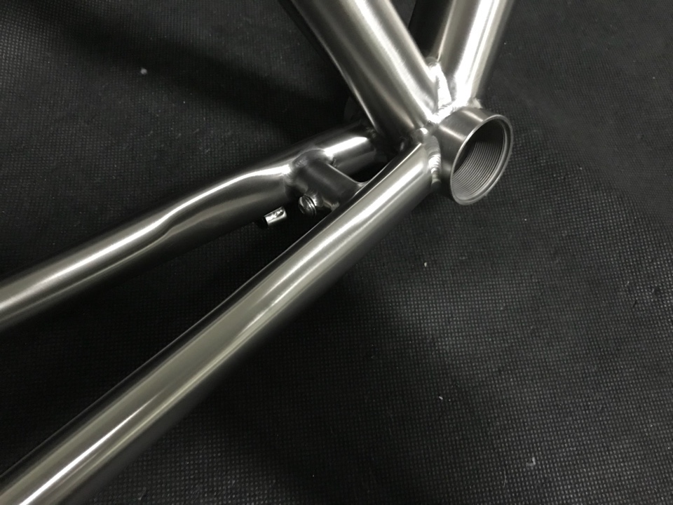
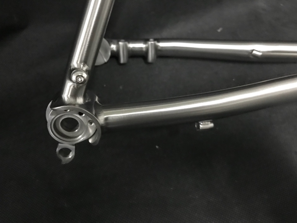
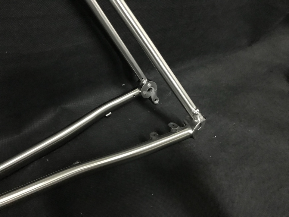
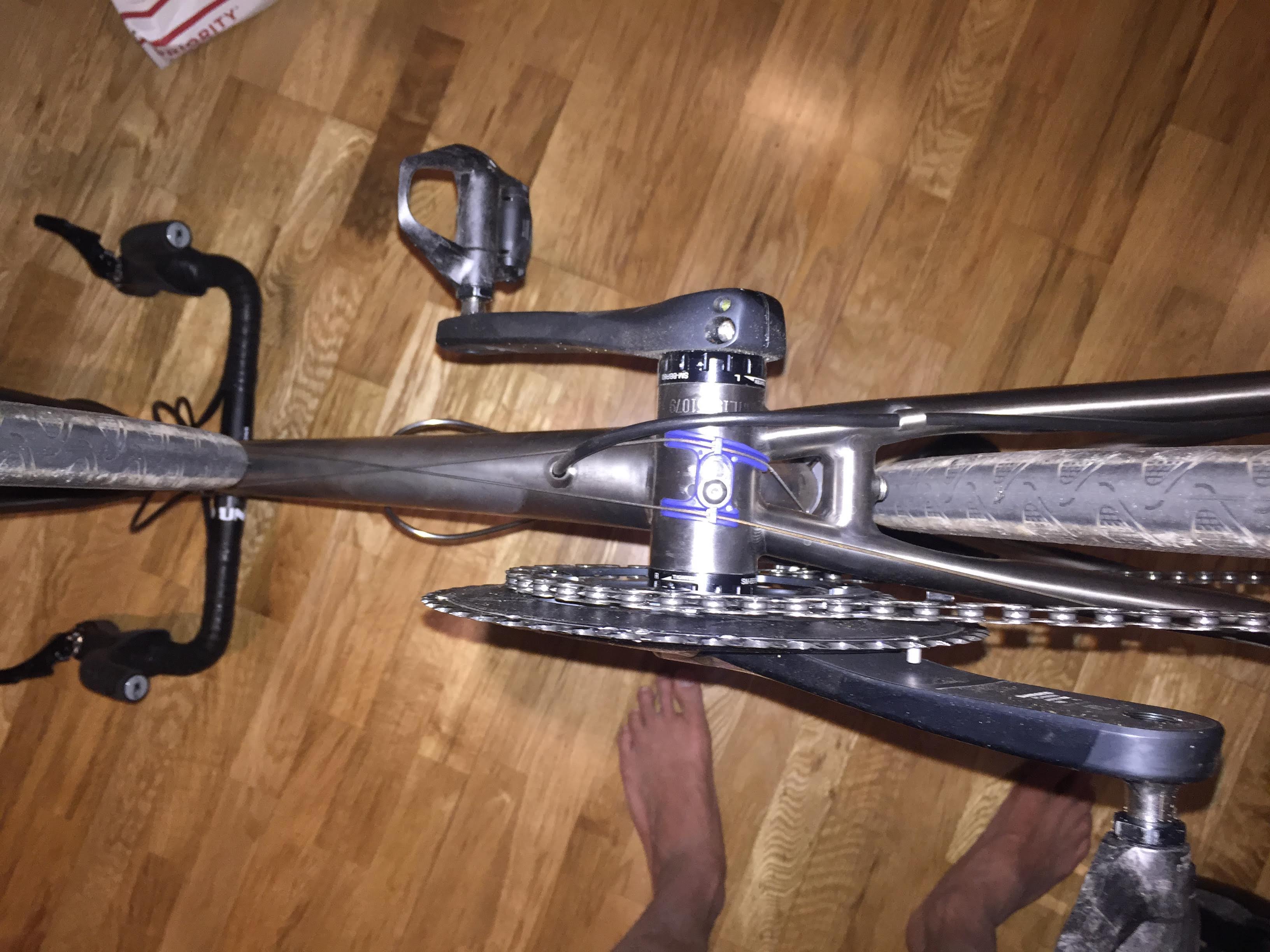
When I initially specified this design to Sumi, she sent me back a drawing that showed just the beginnings of an internal guide tube for the rear brake hydraulic hose, but not the full guide tube. I asked her what’s up with that and she explained that they don’t do the full guide tube anymore to save weight.
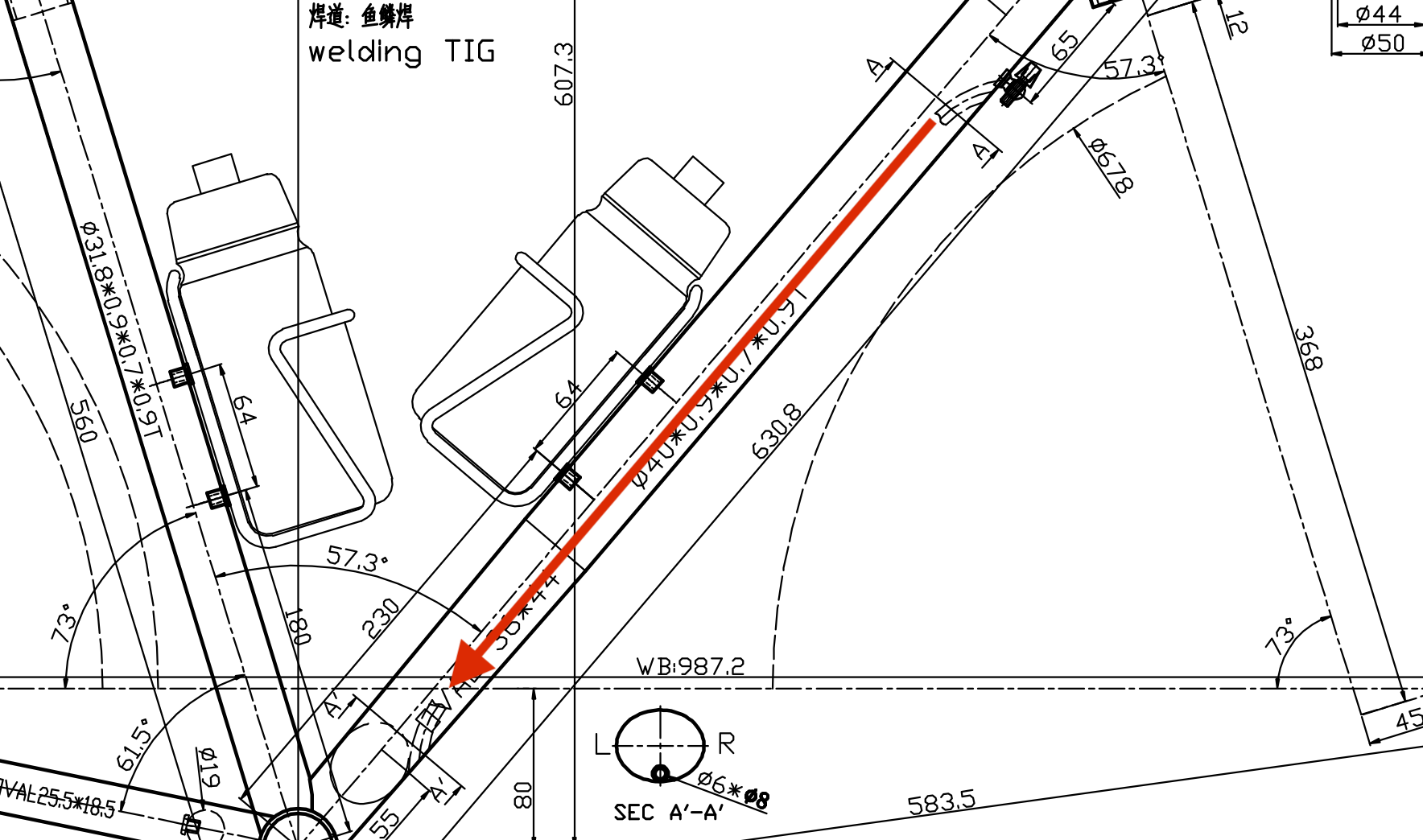
A thick inflexible hose needs to make its way through the dark abyss of the downtube.
I searched online for methods of routing the cable through two random holes in the frame, which seemed impossible. Pushing in one end of the cable was easy, but how would it come out the other end? I found a video that showed a “vacuum cleaner + thread” method. Basically you insert some sewing thread into the frame, then use the suction of a vacuum cleaner on the other hole to pull the light thread through. Then tie the thread to the cable end to pull the actual cable all the way through. So I approved the design choice based on this future technique I’d use, and now it was time to put it to the test.
I had no sewing thread, so I substituted dental floss. The vacuum cleaner surprisingly very easily pulled the floss through to the other hole, but now came the hard part. I tried several methods of tying/taping the floss to the real cable and pulling it through, but the floss would repeatedly break once it came time to pull the hose end through the second hole. I even tried triple-weaving the floss together into a super strand, but that broke just the same.
I was ready to give up and bring it to a local bike shop to see what ideas they had(hoping they wouldn’t say “you’re SOL, just ziptie the cable to the outside man), when I had an idea of my own. My issue was the floss would break, so I needed something stronger than floss. What’s a strong, thin flexible cable? A wire brake cable. It was a bit ironic that I was using a wire brake cable to route a hydraulic fluid brake hose. So I got the floss through, then used the floss to pull a thin wire brake cable through, and then use the wire brake cable (which can withstand a lot of force) to finally pull the hydraulic cable through. Even this required 4-5 attempts because the duct tape that held the brake cable to the hydraulic cable also kept coming apart, so I needed to shape the duct table into a cone-like structure to reduce friction as much as possible, to finally pull the hydraulic hose through, shout in exultation, and call it a anight at 1AM.
*Almost a fully working bicycle
The Build Day 2
Day two was mostly about setting up the hydraulic brakes and shifter cables, as nearly all the other components had already been attached.
Hydraulic Brake System
One of the biggest unknowns with this build was the hydraulic brake system. All the previous components had analogs with bike maintenance I’d previously done. For example, setting up the front and rear derailleurs was new, but it was based off metal cable management, which I already had experience with when dealing with wire brakes. But the hydraulic system was a complete enigma to me, I was only 60% sure I had actually purchased all the parts I needed. Before I even began this task, I read the Shimano hydraulic system guide about 5 times over, then watched several YouTube guides (1, 2).
The actual setup procedure wasn’t the worse, it basically consisted of:
- the hose was already pre-inserted into the brake calipers, so I just had to worry about the brake lever end
- cutting the hydraulic hoses to length with an X-acto knife and trying my best to make a perfectly perpendicular cut
- hammering in a hydraulic insert into the newly cut hose end
- ensuring there’s an olive in the brake lever hose
- inserting the hose, and tightening screw until no more oil leaks out
Then follows the brake bleed–the basic idea is to push more hydraulic fluid into the system using either a funnel at the top of the brake levers or with a syringe down at the caliper. It was quite a complex messy task where mineral oil got everywhere. It was quite worth it in the end though, as the hydraulic brake system brings the bicycle control to another level.
Derailleur Shifters
I spent awhile setting up shifter cables, as I’m quite OCD about getting the settings perfect. I’m the type of bicyclist who adjusts his brake cable settings mid-ride. Luckily adjusting derailleur cables is just a matter of setting limit screws, then adjusting the indexing until the shift feels like its at its local minima for effort. I largely followed this excellent Park Tools video guide.
And now I was done with the cabling, the bike was nearly fully functional at this point, but it was already 3AM, and the finish line would need to wait another day.
neat cabling job
The Build Day 3
The next day, I screwed on a set of pedals, adjusted the seatpost and saddle, and gave it the first test ride.
real handlebar tape unecessary for an initial test ride, just duct tape :)
Continue reading for Part IV - Completion, showing the complete build and describing my first long distance ride.